
Here we look at some of the features of this circuit and pin functions. The circuit is working fine alone.

Pin by ROBERTO APARECIDO DA SILVA on charge Electronic
After the desired delay time, the contents of the memory are converted back into an analogue signal.

Pt2399 echo circuit board. Ic pt2399 from princeton technology corporation. The pt2399 basic echo circuit is the one where the delayed output is fed back to the input to produce echoes. Testing a pt2399 using the echo schematic.
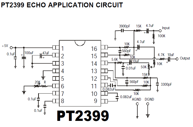
Decay time, room size, dry/wet balance, and the output level. The main difference between the delay and the echo circuit is that the echo has a feedback path between the output (pin14) and the input (pin16) 4.1 pt2399 input stage. Pt2399 basic echo circuit simple voice electronics lab com digital stereo mixer projects effect with ic 4558 preamp board for microphone mic pre amp based lm358 audio circuits dc 12v sound mfos rockit producer processor 3 input multiple controls diagram hobby under repository changer dot gen repeter.
Pt2399 v1.6 2 february 2010 application circuit echo note: Pt2399 is a typical karaoke echo processing integrated circuit.it is widely used in cd, vcd, dvd, tv and karaoke machines. This is the new ebay.
When the value of the resistor (r) increases, the range of the delay time also increases. For the actual hardware, here is the schematic diagram of the reverb pedal circuit (figure 6). Order parts online with confidence at partstree.
Furthermore, the level of attenuation in the feedback loop is set by the repeats control potentiometer. Ad same day shipping most orders. Pt2399 echo/delay chip used in many diy and commercial pedals.
Engineers and hobbyists alike can use this basic design to modify it for their own purposes the pt2399 echo processor ic is a very versatile circuit with adjustable input/output filtering, delay length, wet/dry mix, and a lot of unexplored potential!. I'm using my yamaha mixer's auxillary output to feed the input of echo circuit and the output of echo circuit is fed to another channel (say echo channel), the mic is plugged into another channel of the mixer. Ad over 70% new & buy it now;
It will consist of two circuit boards. The recommended resistor value(r) is 10 k ω. The pt2399 is a single chip echo processor ic utilizing cmos technology.
This replaces the original mitsubishi device described in project 26.the pt2399 has been around for a while now, and. External resistor having a value of 10 k ω to 50 kω may be used. Pin 15 and pin 16 to form a capacitance by changing the external resistance to change the input frequency response of the inverting amplifier, as the signal input.
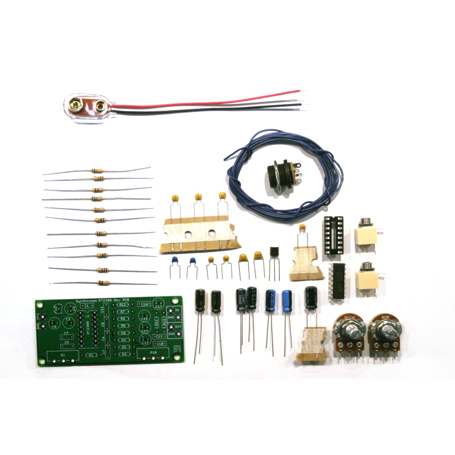
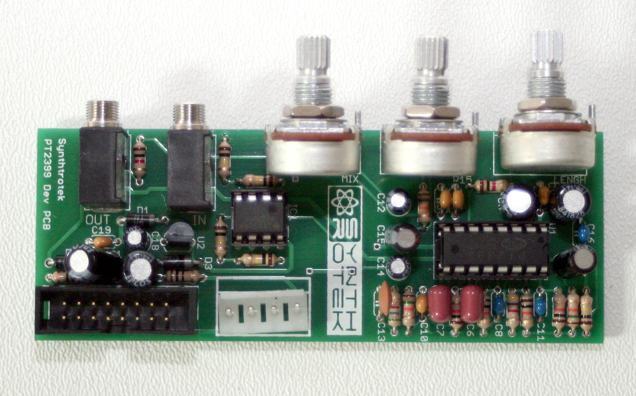
Pt2399 echo and reverb basics. The pt2399 is an echo processor ic manufactured by the princeton technology group. The first step in any successful diy electronics project is to make sure that you have all of the parts and know their reference id for proper board placement.
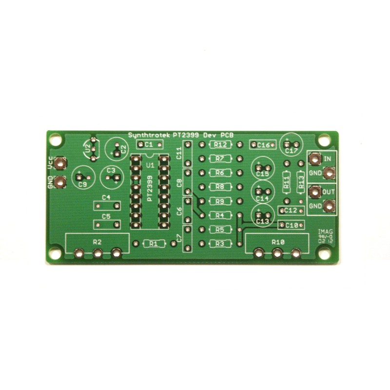
Welcome to synthrotek pt2399 dev delay assembly instructions! But i'm using a mixer to feed the input. The delay circuit is shown in figure 1, and uses the princeton technology pt2399 digital delay chip.
Digital echo circuit pt2399 digital echo processor ic pt2399 is using cmos technology in audio purposes. I believe what they mean by 'surround' is reverb, which is actually sort of achievable (more on this later in the mods section) if you set your circuit up right. Digital echo processor pt2399 is implementing the system in.
Limited time sale easy return. Please refer to table 1 for the resistor/delay time values. It is used for audio signal amplification and effective processing.
I know i won't get same long delays as with the pt2395, but my new idea is to build a dual pt2399 delay. Minimal external components are required for use and delay time is set with resistance. (super discount) us $6.96 42% off | buy microphone echo circuit board pcb audio sound tone control mic delay pt2399 ne5532 diy from seller shop912225095 store.
Pt2399 echo application circuit the second schematic princeton has on their datasheet is the pt2399 surround/delay application circuit. Find pt2399 circuit board now! Echo dot gen 3 microphone disable circuitry colin o flynn.
Pt2399 echo, reverb effects schematic circuit. Great service & same day shipping. Shop quality & best amplifier directly from china amplifier suppliers.
The pt2399 is in a dip 16 package. Each one will have the following: I'm using pt2399 ic for my echo circuit as shown in the application circuit.

Pcb Pt2399 Echo Circuit Diagram Schematics Com Fv 1

Pt2399 Echo Circuit Pcb Echo Reverb W Amplifier / The

Low noise echo repeater PT2399 Ifi_Project e03 Class D
Pcb Pt2399 Echo Circuit Diagram / Piezos Electrets Pt 4
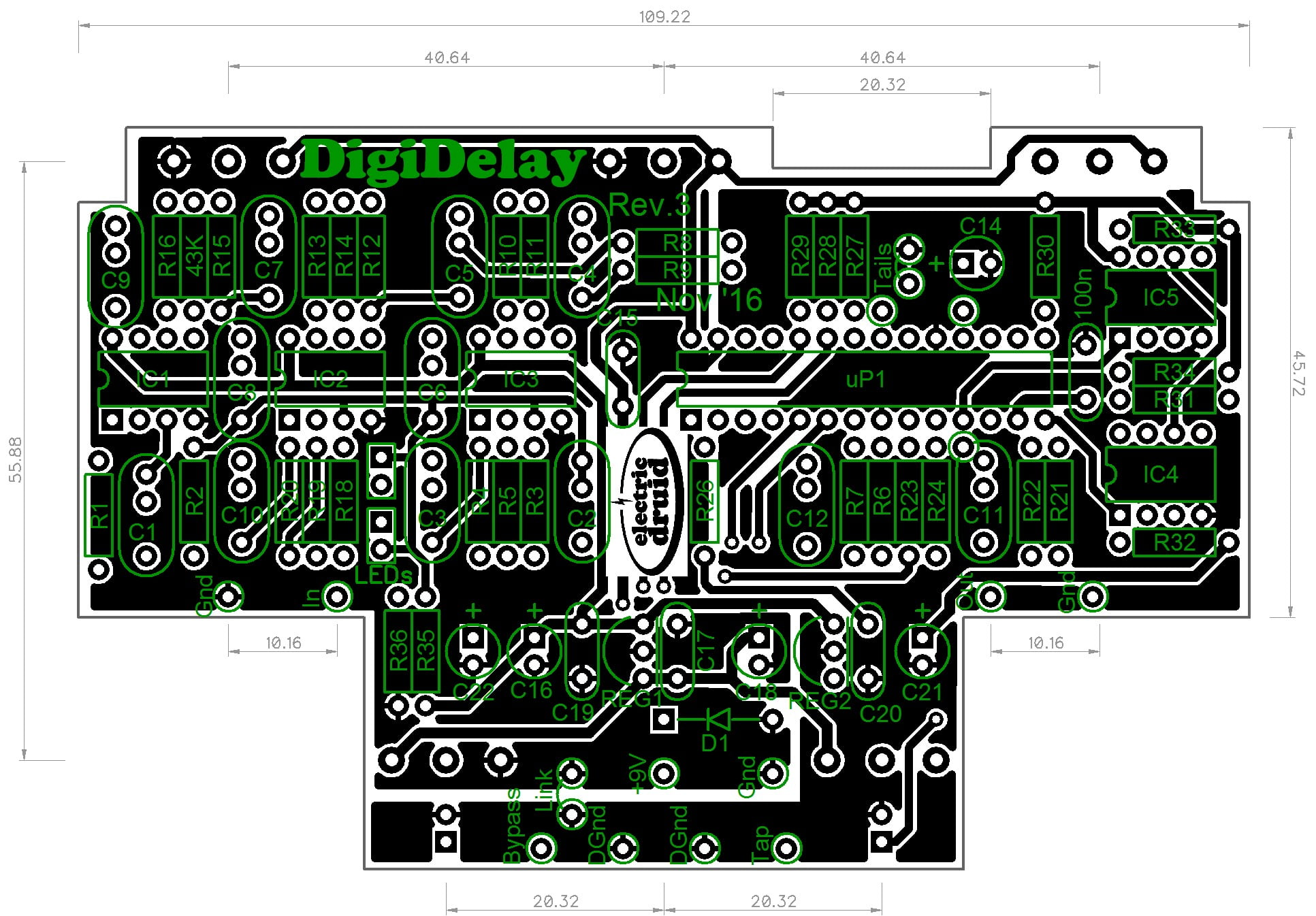
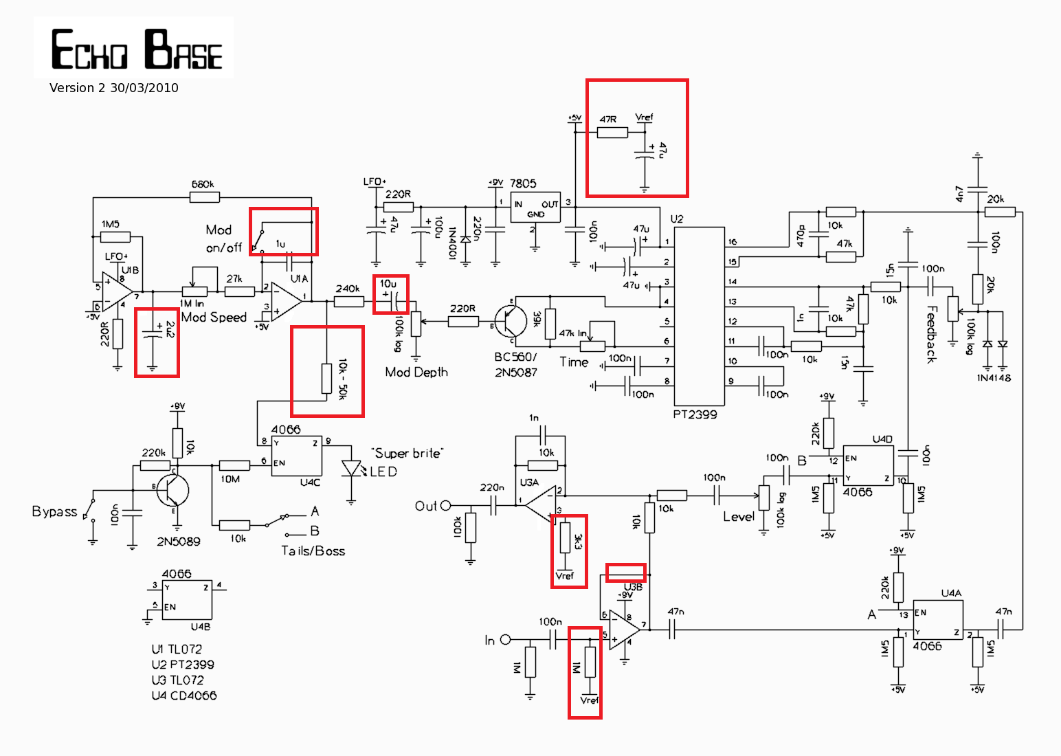
Echo Base a new PT2399 delay

PT2399 Echo PCB Only (Local) Scion Electronics
IC ECHO PT2399 dientuminhquan


PT2399 Microphone Amplifier Board ( XHM273 Dual Channel

pt2399 echo Formigas, Guitarras ศึกษา, อิเล็กทรอนิกส์
PT2399 Echo Delay Second Hand Synth
Synthrotek Pt2399 Delay Dev Board! Synthrotek

Digital Echo Circuit PT2399 Electronic Circuit
Pcb Pt2399 Echo Circuit Diagram / Piezos Electrets Pt 4

PT2399 Dev Delay Synthrotek

Rangkaian Mic Echo Digital Sederhana Dengan IC PT2399

Pcb Pt2399 Echo Circuit Diagram Digital Delay Unit For
PT2399 Echo Application Circuit DIY Audio Circuits
Modular PT2399 Delay (16mm) Synthrotek

Integrated Circuit PT2399, Echo / Delay CE Distribution